A digital watch made with a custom circuit board and the STM32L0. Made to push the limits of low power wearable technology and my hardware skills
This almost became a very different project. After getting a large order in from LCSC, I wanted to try using the CH32 microprocessor (otherwise known as the 10 cent microcontroller) in a project. The first draft was a lot smaller in scope and after running the numbers, I realized that it just wasn’t up to driving a display and taking input.
After doing more research, I came across the STM32 line. These are similar to ESP32’s, but drop wifi and bluetooth for a much larger focus on battery and power efficiency. This version kept the same feature set and made it all the way into the production phase before a fatal flaw in the power section was noticed. (subtle foreshadowing)
After designing the first PCB, I took a step back and reevaluated the project. I added more sensors, an Inertial Measurement Unit, a magnetometer, and a Real Time Clock. The main focus though was on the power section
The flaw from earlier comes from how to deal with charging a battery over USB. When running off battery power, the system needs to turn anywhere from 4.2-3.0V into a stable 3.3V. This requires a buck-boost convertor and a load of filtering. The biggest problem comes when plugging in the 5V USB. It not only needs to charge the battery, but also power it when plugged in, because batteries don't like being charged and discharged at the same time. The old design didn’t account for either of those issues and I hoped that I had fixed those in this version (more on that later)
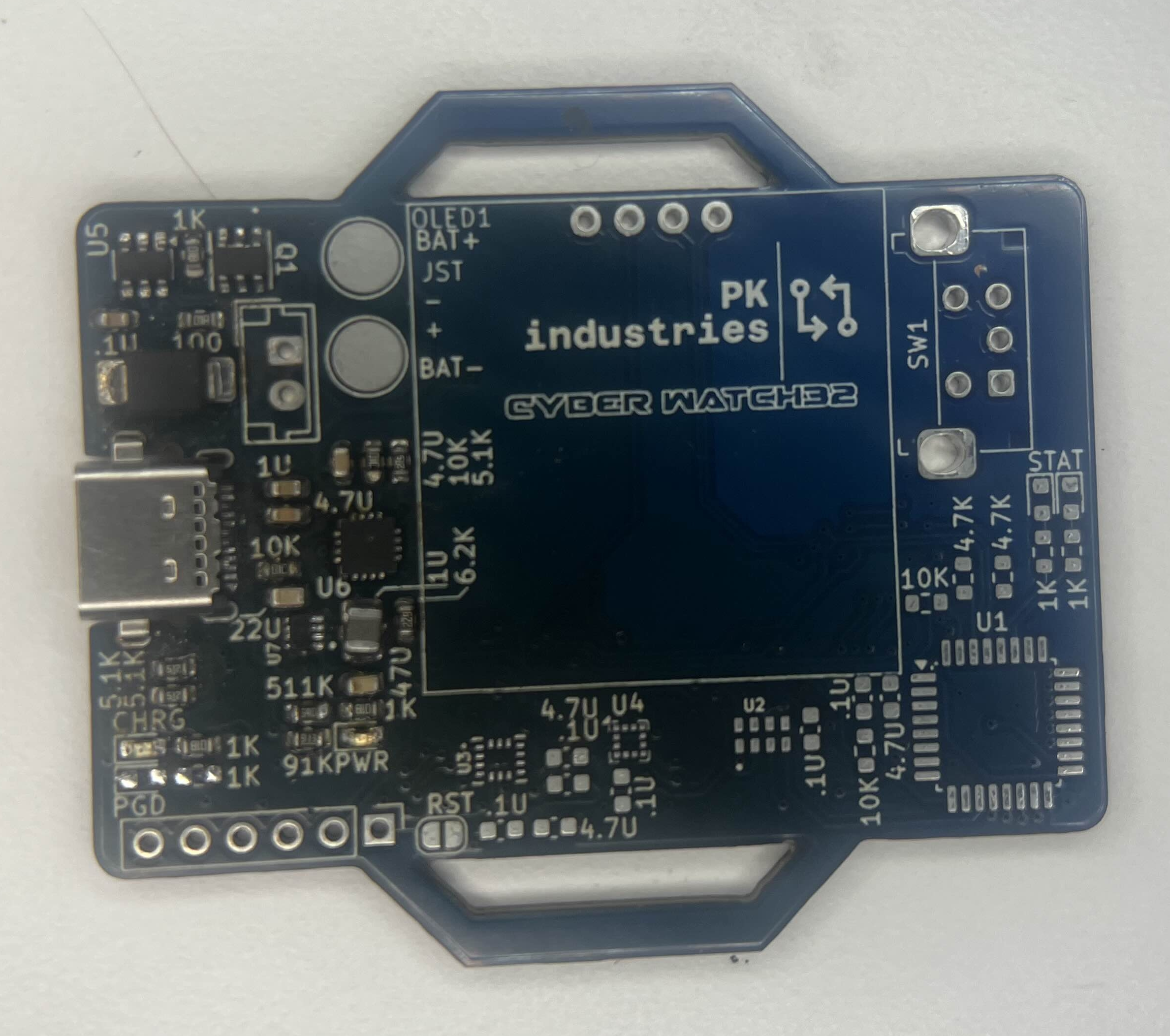
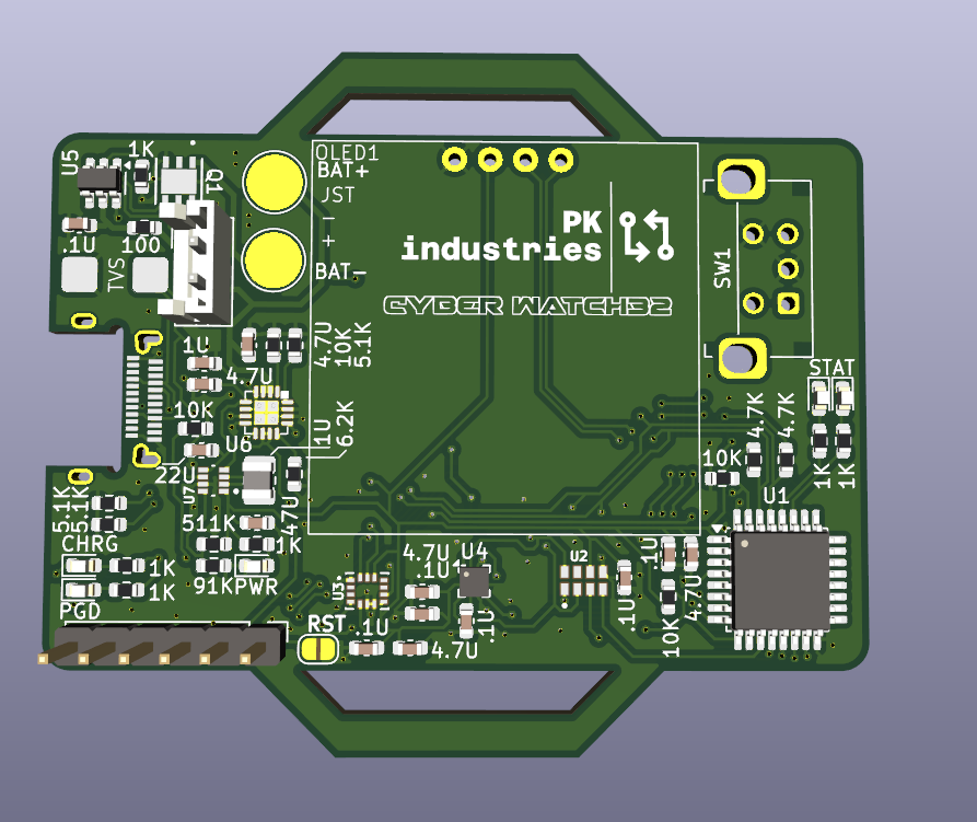
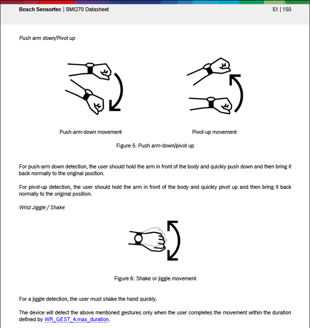
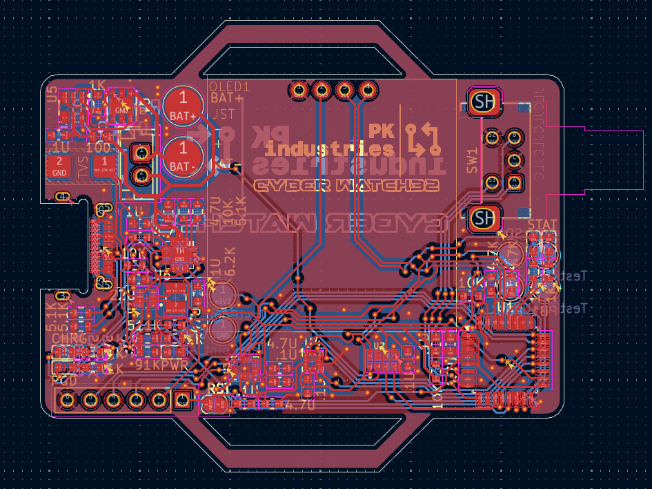
In addition to the STM32L010K8 main processor there are three sensors, a 128px OLED and a side mounted rotary encoder. The RV3032 C7 is both “the most accurate real time clock” and has a temperature sensor, working over I2C. The IMU is the BMI270 from… Bosch? Yeah the german power tool company also makes semiconductors. The LSM303 magnetometer provides a compass as well as another IMU, with less features, in order to correct the readings.
After designing the entire board once already, I was determined to make this board the best possible and take my time so I didn't have to have a 15 day+ delay from ordering and shipping the PCB. The board is sectioned off into power management on the left side, and logic on the bottom right. There are a lot of traces on the board, with all but 6 pins of the MCU being used. In total 140 vias are used and everything just barely manages to fit in 2 layers. There are also cutouts in the top and bottom for a watch strap.
Now this is the reason why the project is still in progress. The chips were way smaller than I expected, and even with a hot plate and stencil I couldn’t get a good assembly. The first one lit up the charge LED, but the power regulator got bridged and broke. The next two didn’t even light up and just shorted the USB. I think the problem comes from the uncommon USB C port I used, and the second row of SMD pads are bridged and I just can’t see it, but for now the project is on hold.